Assumption in theory of simple bending of RCC structure(working stress method)
1. A section which is plane before bending remains plane after bending.
2. The concrete and steel reinforcement are perfectly bonded .
3. All tensile stress are taken up by steel and non by concrete.
4.the stress strain relation of Steel and concrete under working load is a straight line.
5. The modulli of elasticty of Steel and concrete are constant.
6. The modular ratio has the value ![]()
,where. 
Is the permissible compressive strength of concrete in bending in Newton per mm square.
7. There are no initial stress in steel and concrete.
CONCEPT OF TRANSFORMED OR EQUIVALENT SECTION


ANALYSIS OF SINGLE REINFORCED BEAM

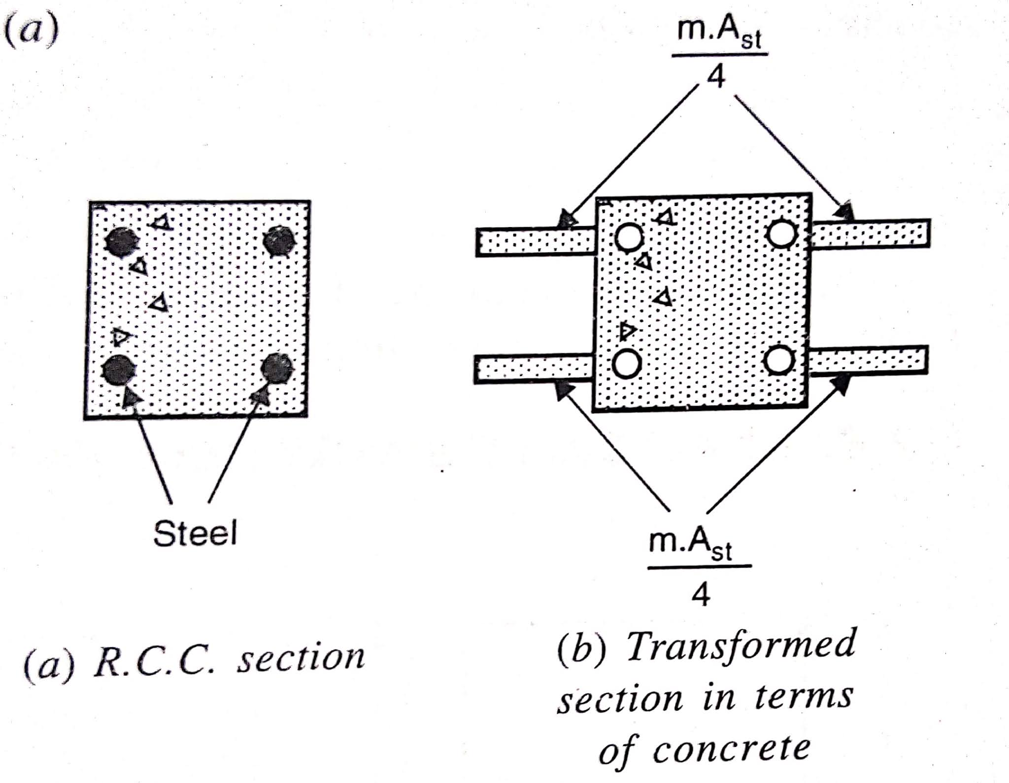
A SINGLY REINFORCED BEAM SECTION IS SHOWN IN FIGURE 2.3 (a). To analyse this section it is necessary to convert it into a transformed or equivalent section of concrete.
Equivalent or transformed section
As per the assumption (3) all the tensile stresses are taken by steel and done by concrete that is the concrete is in the tensile zone is correct. So the concrete area below the neutral axis is neglected and effective area or equivalent area of the section in term of concrete is shown in figure 2.3 b. Violent area is equal to the area of the concrete in the compression zone and an additional concrete area
of concrete corresponding to Steel area
 .
..
Strain diagram
As for the exemption one of elastic theory the strain distribution is linear with the value zero at the neutral axis and to maintain at the top and bottom fibre. The strain diagram for the given RCC section is shown in figure 2.3 c.
Stress diagram
as per the assumption of the elastic theory the stress strain relationship is linear for concrete. So stress diagram is also a straight line with value zero at the neutral axis and varying linearly with the distance as shown in figure 2.3 d.
Maximum permissible stress at the top most fibre in concrete =
Maximum permissible stress in steel=

Maximum stress in equivalent concrete area at the level of Steel=
Note
1. The suffix cbc in. ![]() Stands for permissible stress in concrete in bending compression.
Stands for permissible stress in concrete in bending compression.
2. The suffix st in. Stands for permissible stress in Steel in tension.
Neutral axis (n)
Neutral axis lies at the centre of gravity of the section and it is defined as the access at which the stress are zero. Divide 16 into tensile and compressive zone. The position of the neutral axis depends upon the safe of the section and the amount of Steel provided. The position of neutral axis of any rectangular section can be found by the following method.
1. Stress in concrete and steel are known


2. Dimension of beam and area of Steel are known

Percentage of Steel

Lever arm
Lever arm is the distance between the resultant compressive force and the resultant tensile force. It is denoted as a in the stress diagram.

Moment of resistance
moment of resistance is the resistance offered by the beam against external load. As there is no resultant force acting on the beam and the section is in equilibrium the total compressive force is equal to the total tensile force. these two forces will form a couple and the moment of this couple is equal to the registering moment or moment of resistance of the section.

Balanced section
balance section is that in which stress in concrete and steel reach their permissible value at the same time . This means that stress diagram is as shown in figure 2.6 be. The percentage of Steel corresponding to the section is called balanced steel and the neutral axis called as critical neutral axis.

Under reinforced section
in under 14 section the percentage of Steel provided is less than that provided in balance exam so. So the actual neutral axis will shift upward as shown in figure. in under reinforced section the stress in steel first reaches its permissible value while the concrete is under stressed. The moment of resistance of the section is calculated as

The various features of under reinforced section are as follows
1. Steel is fully stressed while concrete not.
2. The actual neutral axis lies above the critical neutral axis.
3. The percentage of steel is less than the balanced section hence sections is economical.
4. Ductile failure.
5. The moment of resistance is less than balance section.
Over reinforced section
1. Concrete is fully stressed while steel is not.
2. The actual neutral axis is below the critical neutral axis.
3.the percentage of steel is more than the balance section so the section is uneconomical.
4. Sudden failure .
5. The moment of resistance of overreinfornced section is calculated as


Comments
Post a Comment